
Background
Recently I purchased a used Heathkit SB-200 amplifier from the DELARA radio club and after letting is sit on a shelf for a few months, I fired it up and immediately noticed problems. With a fair amount of troubleshooting, I discovered the HV power supply board was definitely not up to snuff.
Here and here are a couple of thread on groups.io which detail the discussion. See my previous post, A Dirty relay on a clean Heathkit SB-200, which improved the SWR “Chatter” problem, but skated around the root cause of the problem.
High Voltage Supply Board Problems
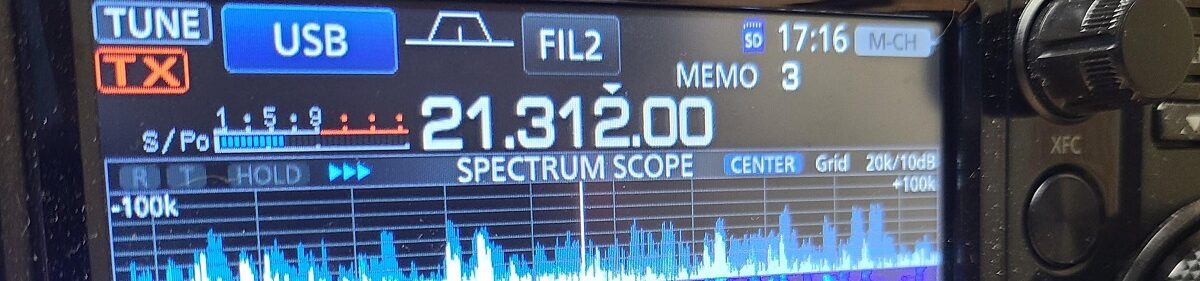
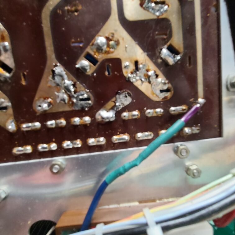
The HV meter on the SB-200 would fluctuate widely, and occasionally swing all the way down to 0. The PCB showed visible signs of damage from a past modification to replace the HV capacitors and a couple of capacitors looked to have small “bulges” on the top. This meant they likely saw abuse in the past.
With that information in mind, I bit the bullet and purchased the Harbach PM-200 replacement module.
The assembly guide provided by Harbach was decent, and a lot of thought is put into making the assembly process easy for most skill levels. However, it lacks illustrations and small details to make the process easier for amateurs that may be new to electronics assembly. Here is my attempt to add some additional information.
Tools
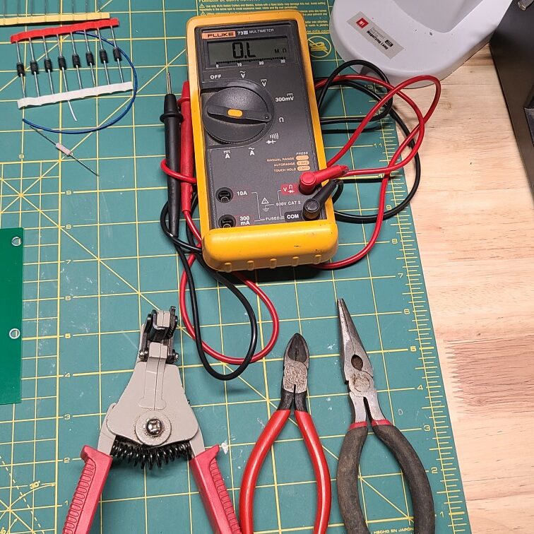
Only a few tools are required for assembly, at a minimum, you need a good soldering iron with a fine tip point, wire cutters, needle nose pliers, wire strippers and tape. For reasons to become obvious later, keep the shipping box the kit arrives in do not discard it yet.
Optionally, a decent Multi-Meter, desoldering wick or pump will come in handy for component checks and cleanup if you make a mistake. These items are not required, but will help if you need them.
Any type of soldering iron rated 60 – 100W, with good temperature regulation, and a fine point tip will work fine for assembly . I use a Chinese made Auyoe 2901 I purchased a very long time ago which has given many years of reliable service.
I recommend using a small diameter, standard 60/40 Rosin core solder, as it is much easier to work with (I use .032″). Stay away from the lead free stuff, it requires much higher melt temperatures, does not flow well, and requires care to prevent component overheat during assembly.
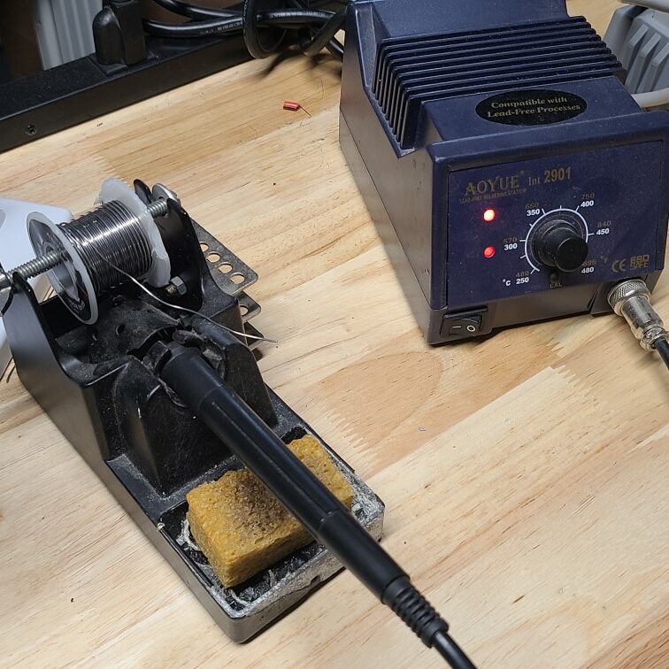
Needless to say, make sure you are working with a clean soldering tip and keep in clean as you assemble. I like to use a small wet kitchen sponge and rub the hot iron after every 15 – 20 solder joints.
Unpacking
Start by laying out all of the components, take inventory, and verify component values.
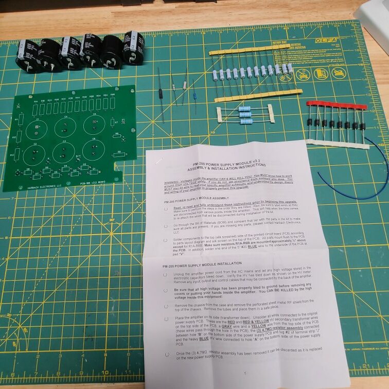
Page #4 of the Harbach manual lists the components along with the reference designators where they are installed. If you have a multimeter, verify all components are to spec with a multimeter also. If you do not have a multimeter, a quick read of the component values printed on the device will suffice. For resistors, decode the color bands to determine if their value is correct.
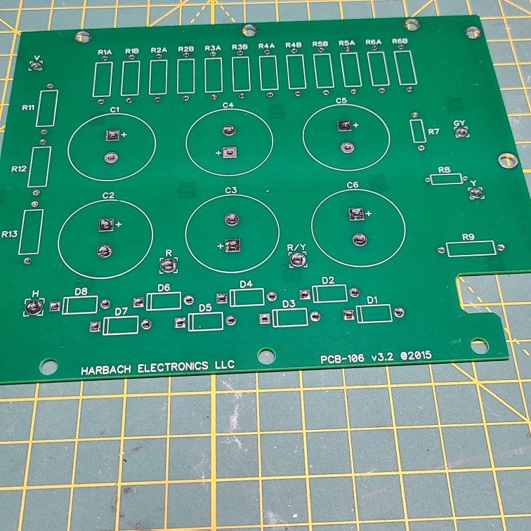
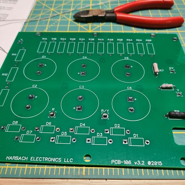
Next, perform a quick inspection of the PCB, verify all pads are intact and no gouges or scratches are present.
Assembly Steps
- Bend all components leads using a set of needle nose pliers before insertion, this makes insertion and soldering much easier.
- Start with the smallest parts first and then work towards larger parts. This prevents them from falling out or separating from the PCB when you turn it over to solder.
- Recommended assembly order for components
- Resistors R7 – R9
- Diodes D1 – D8
- Resistors R11 – R13
- Resistors R1A – R6B
- Capacitors C1 – C6
- Blue Wire
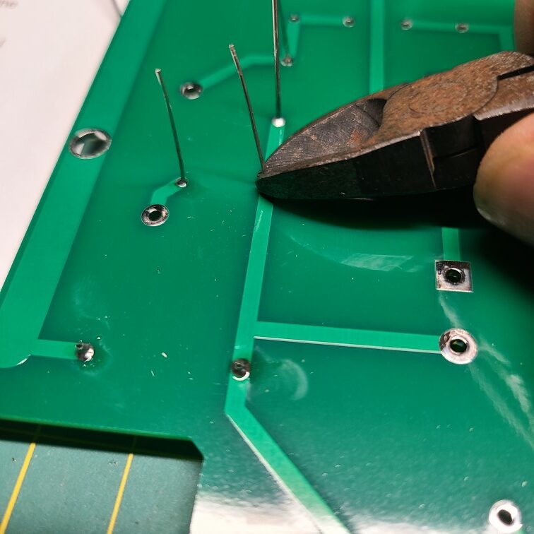
Do not pre-cut the component leads, insert the full length into the PCB and then solder before cutting. This helps hold the components into the board and allows for a perfect cut length.
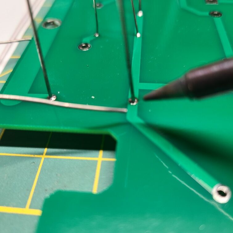
When soldering, heat both the pad and wire at then add solder, do not overheat as it can damage the PCB pad and/or the component. After soldering , trim the lead as close as possible to the PCB.
Resistors R7 – R9
Start by soldering R7 – R9 in place. Polarity is not important in this case so the components may be inserted in either direction. Page #4 of the Harbach manual indicates which component goes in which position.
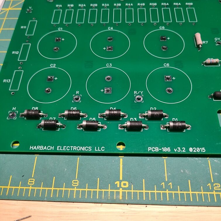
Diodes D1 – D8
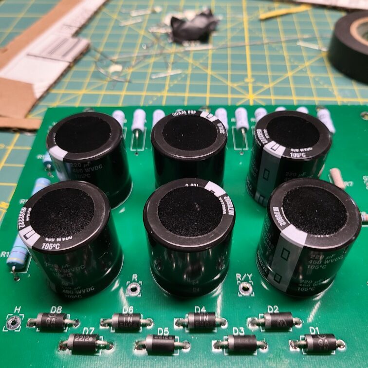
Next move on to D1 – D8, polarity is important in this case, make sure the grey band on the diode is oriented as indicated on the PCB silkscreen as per the following picture.
Resistors R11 – R13 and R1A – R6B
After installing the diodes, install R11 – R13 using the same procedure as R7 – R9.
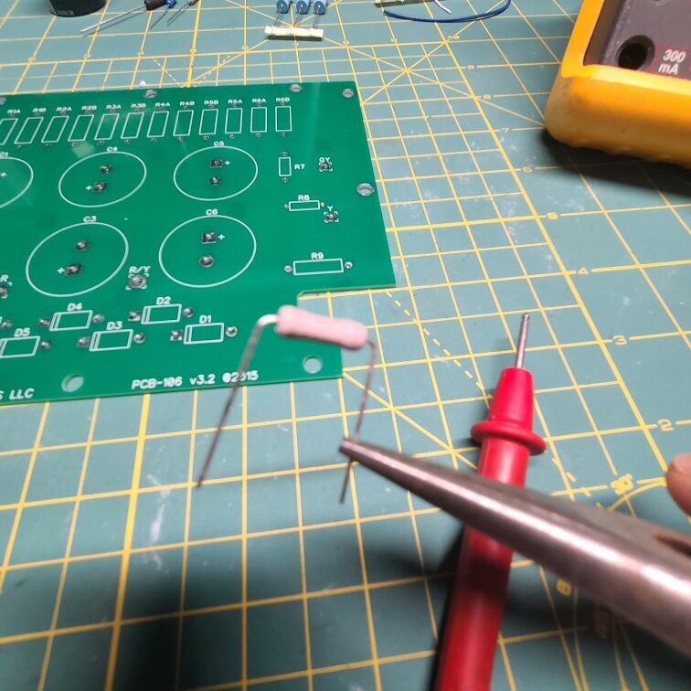
Resistors R1A – R6B require special consideration. These must be mounted at least .25 inch above the PCB to allow for proper air flow and isolation from the PCB.
The shipping box the kit comes in provides an easy method to make a quick spacer.
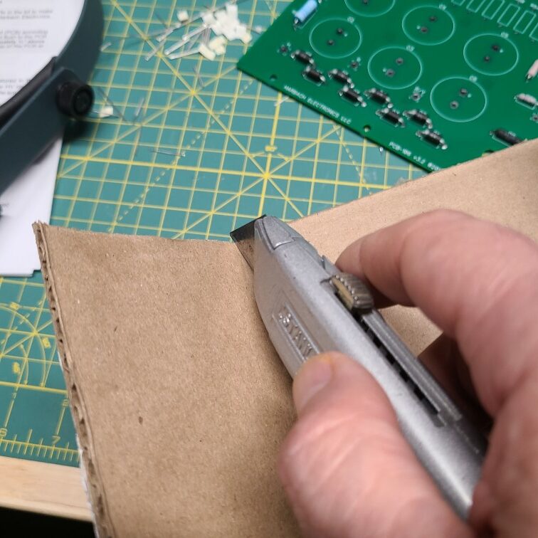
The thickness of the box measures .15 inch. By cutting two strips off of the cover of the box, a quick and easy .3 inch spacer can be made.
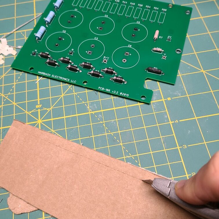
Cut a couple of strips and tape onto the PCB .
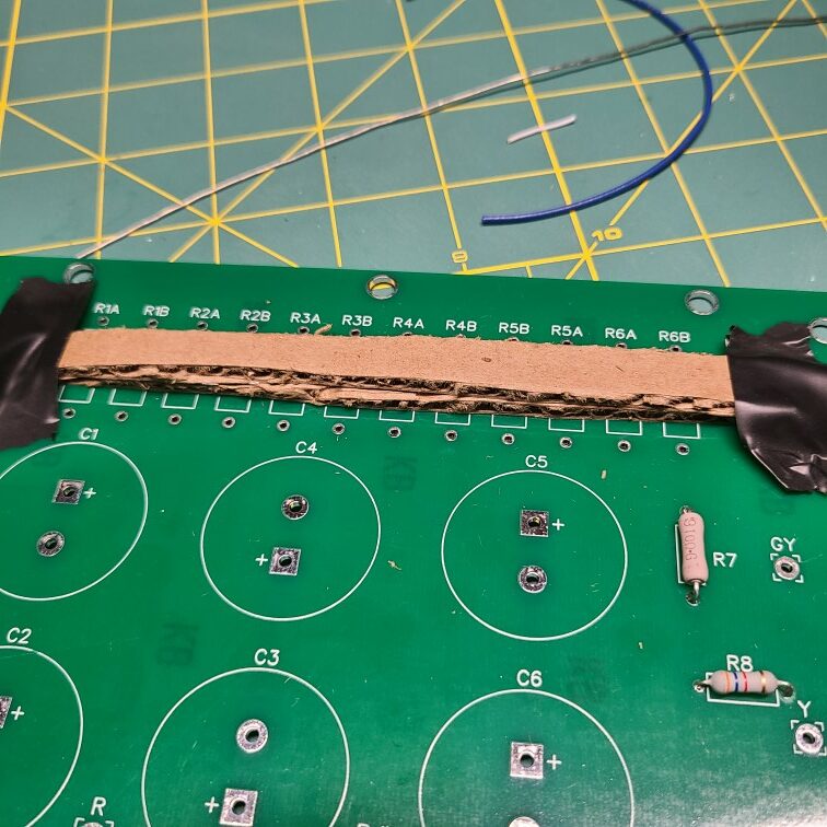
Install the resistors over the spacer and solder into the board.
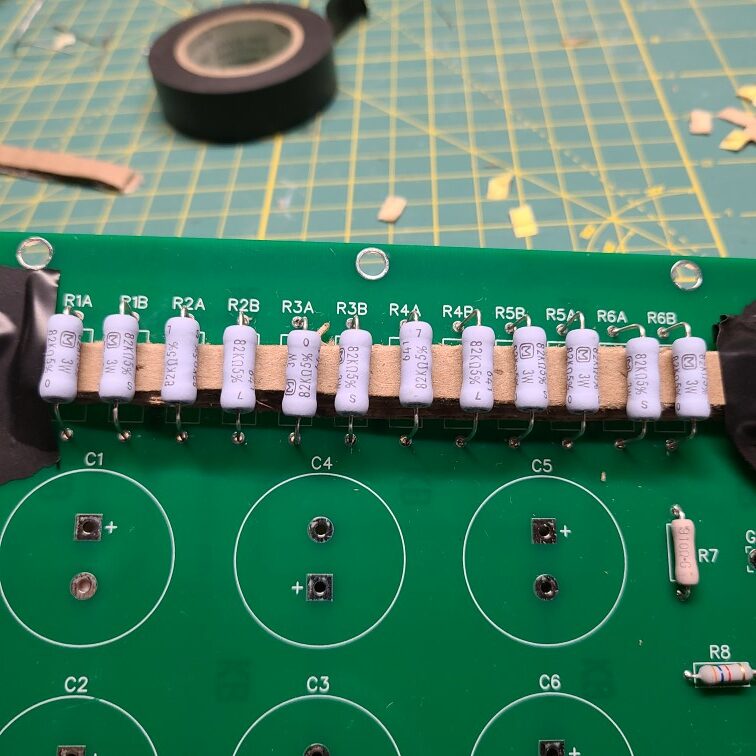
After installing the resistors, clip the leads and remove the spacer. You should have a pretty consistent spacing off the board at this point.
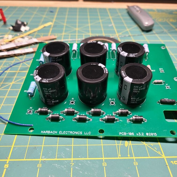
Capacitors C1 – C6
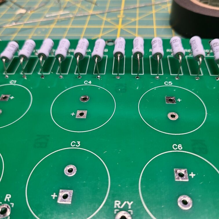
Install the capacitors C1 – C6 next, polarity is very important here, if installed incorrectly, they will likely explode. To identify proper polarity, find the gray band with black squares, the lead nearest to this band is the negative pin and should go into the round hole on the PCB. The lead closest to the black side is the positive will go into the square hole with a “+”.
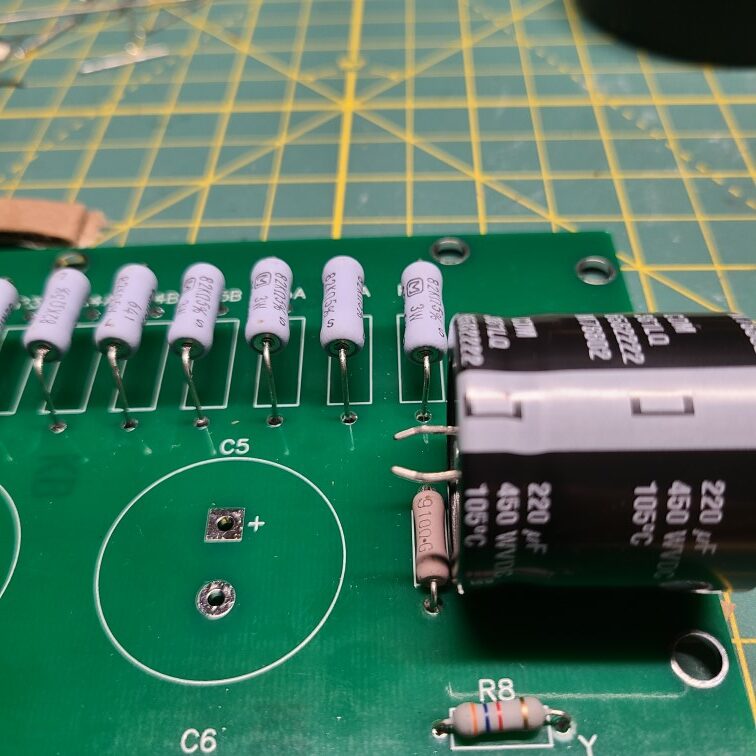
Next, double check the capacitors match the picture below.
Finishing up
Finally, strip a small section of the insulation off of the blue wire supplied with the kit and solder to the underside of the PCB.
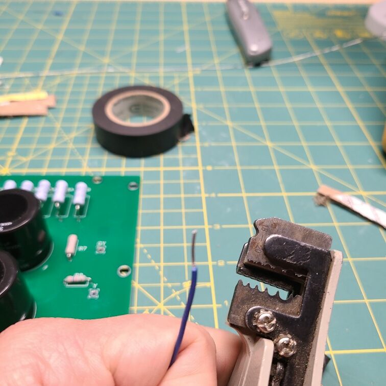
This should be soldered into the hole marked “V”.
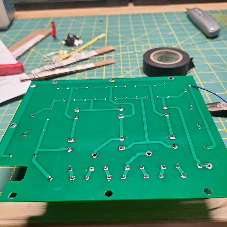
At this point, assembly of the kit is complete, inspect your work and verify solder joints.
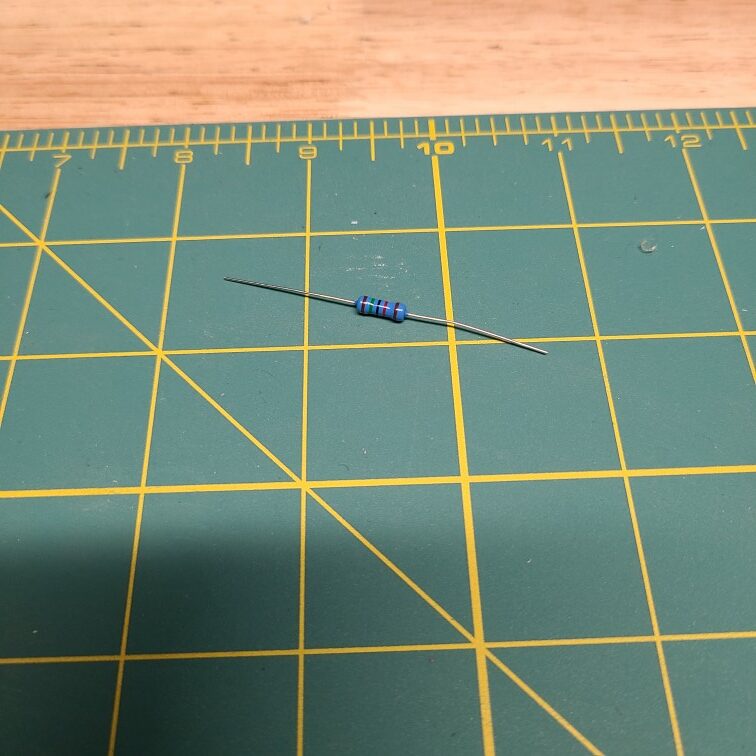
Left over components
You will have one lonely 15K resistor left over from the build. This will be used during the installation process and should be held onto for now.
In Conclusion
Your PCB is ready for install, which I will cover in Part 2 of this series.
73 – AE8Q
One thought on “A New High Voltage Power Board For the Heathkit SB-200”