The is the second of a 2 part series detailing assembly and installation of the Harbach PM-200 replacement board for the Heathkit SB-200. Part 1 can be found here.
With your newly assembled HV board from Part 1, it is now time to begin the install.
Tools Required
- Assorted Screw Drivers
- Soldering Iron
- Desoldering wick or pump
- Wire cutters
- Outlet Strip
- Variac (Optional)
- Isolation Transformer (Optional)
- Load bank (Optional)
Chassis Prep
WARNING: Make sure all high voltage are properly bled to ground before performing the steps listed below. Failure to do so may result in a slow, painful, gruesome death. BE SMART and BE CAREFUL!!!!
Rotate the amplifier onto its side and remove the four rubber feet at the bottom. This step is required as the screws on the rubber feet also hold the chassis in place.
Next, rotate the amp right side up and open the top door to the case
Remove the perforated sheet metal RF shield from the top of the chassis. This involves removal of a lot of screws to keep track of.
Carefully remove the tubes and place them in a safe place away from your work area.
High Voltage Board Removal
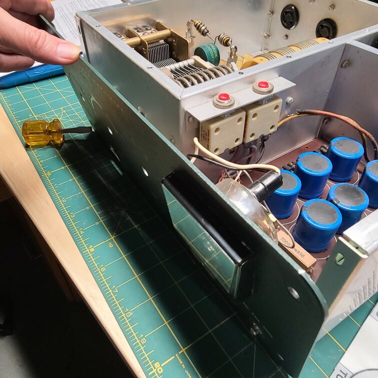
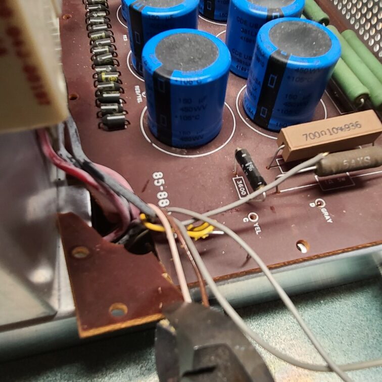
Place the chassis on its side, transformer down and desolder the Red, Red/Yellow, Gray and Yellow wires from the PCB. If for some reason you encounter problem during the removal process, you can clip the wire close to the PCB. Clip only as a last resort as it may shorten the length and the wire will be too short for the new PCB.
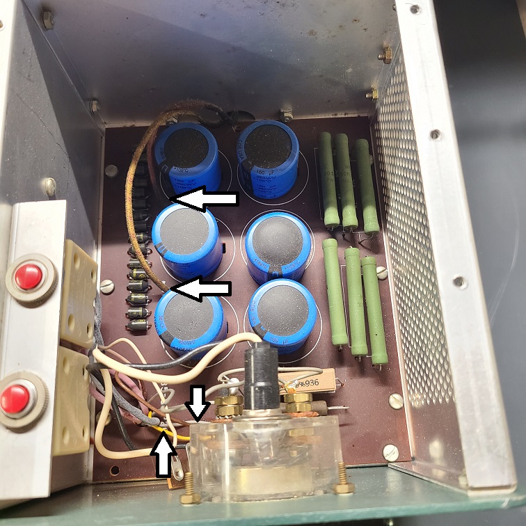
The gray wire is somewhat hidden by the meter, here is a zoomed in picture of it’s location.
Remove the 3 47M resistor assembly. After removal, it may be discarded as it is replaced on the power supply PCB.
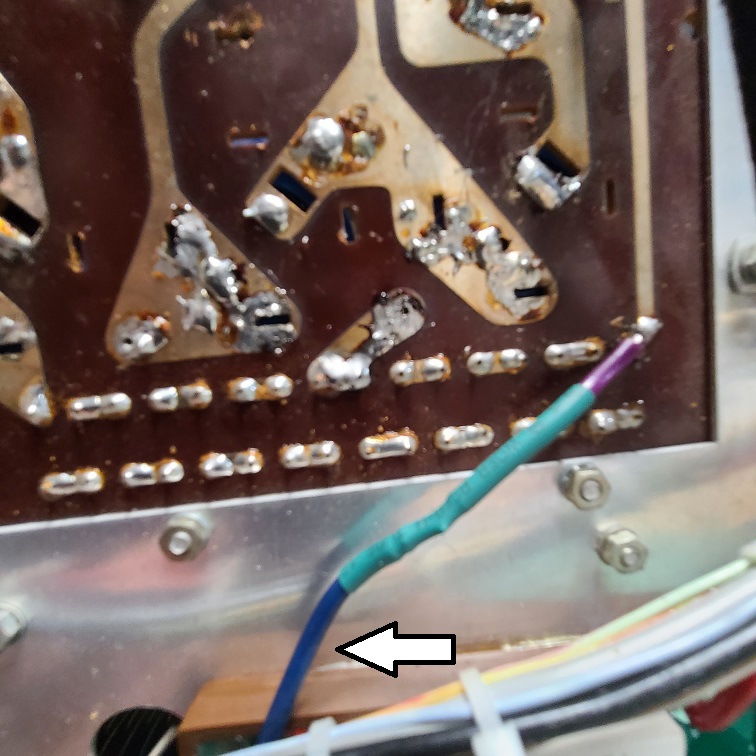
Remove the heavy Blue HV wire as indicated below.
With the wires out of the way, remove the 9 screws, washers and nuts that secure the old PCB. 8 of the 9 screws will be while installing the new PCB.
Removing the control knobs
Remove the control knobs next making note of to their position before removal. Depending upon the age/state of your amp, the knobs may put up a little bit of resistance, try not to damage the heads of the screw as they may be very tight.
Large knob removal
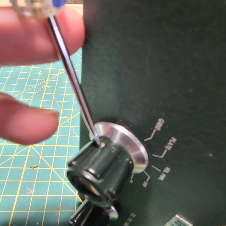
With the chassis right side up, remove the 3 large control knobs, each knob is held on by two set screws.
Small knob removal
Remove the 2 small control knobs, these are secured by one set screw. As before, make note of the position of the knob.
Nut removal
Using a wrench or pair of pliers, carefully loosen the retention nuts on each of the control knobs, removing both the nut and the washer.
Front panel removal
Remove the 4 screws holding the faceplate panel to the chassis.
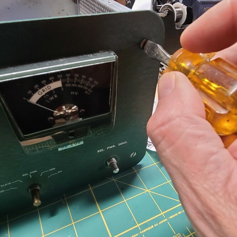
Tilt the front faceplate forward, if stuck to the chassis you may need to pry on it a bit. Keep an eye on the meter wires as you tilt the plate forward
Tilt the front face forward enough to get good access to the front of the PCB. Let it rest on something to prevent damage to the meter wires.
Save some time
A number of wires pass thru a large hole the old HV PCB. Since we will be discarding this board, there is no need to desolder these wires. Lift the front of the old PCB an inch and break off the corner of the board with a pair of cutters to expose the wires.
Carefully remove the old PCB. This will require pulling it forward a bit and then tilting it up to clear the existing wiring and screws.
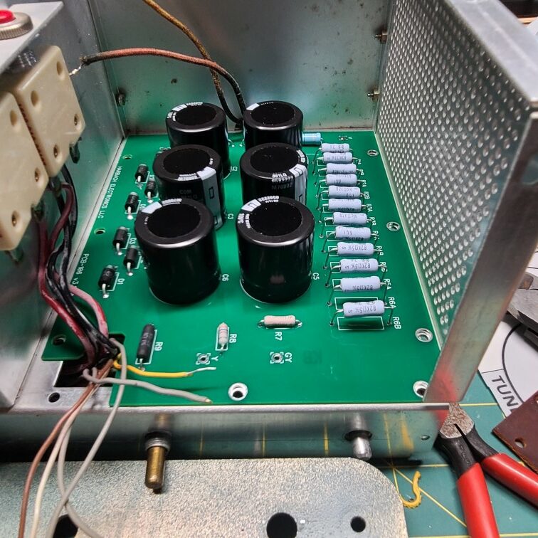
New PCB Installation
Insert the new PCB assembly, this board has a notch cut into it which allows clearance for the meter wires to feed thru.
After the PCB is in place, insert 2 or three of the PCB screws to hold it in place.
Yellow / Gray Wires
Reinstall the Yellow and Gray wires to their respective holes in the PCB. Preferably, route the wires on the top of the PCB and feed thru to the bottom. If the wires are a little short, you can route them on the bottom of the PCB and feed up thru the board.
If the wires are too short in both direction, you need to replace the wires with something longer.
HV Transformer wiring
Reconnect the HV Transformer Red and Red/Red Yellow wires. Use this opportunity to inspect the wire jacket for defects that need repair before moving on.
Turn the chassis back up on its side and replace the remaining PCB screws. The new board requires 8 screws instead of 9.
Blue Wire + 15K Resistor
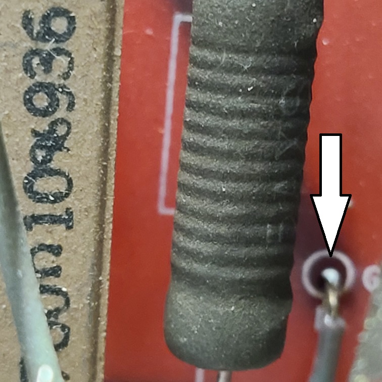
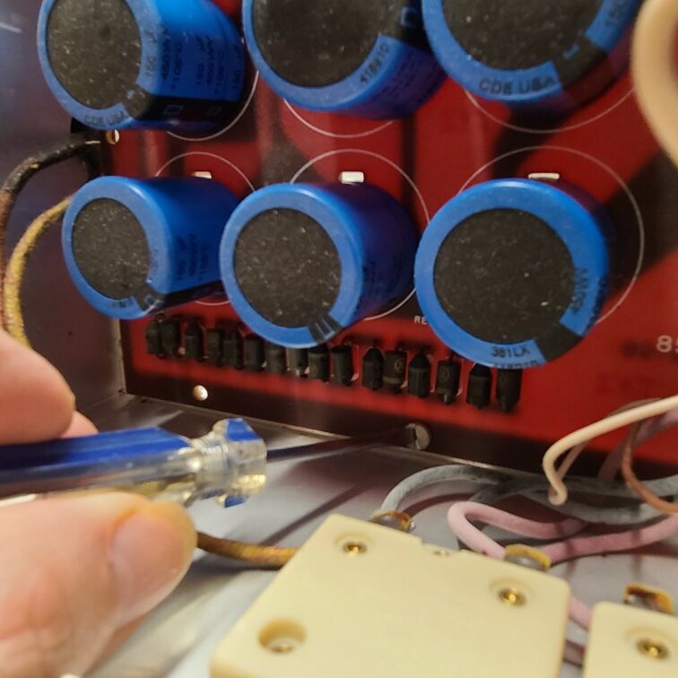
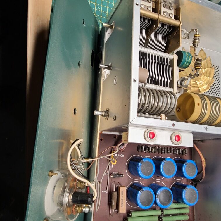
Find terminal strip J near the rear of the PCB on the bottom of the chassis.
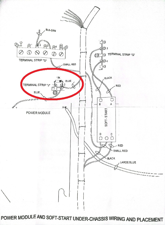
Remove the 15K resistor and clean the terminal strip. The wire to the right should remain connected after the following steps are completed.
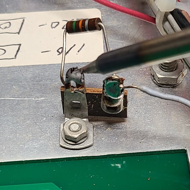
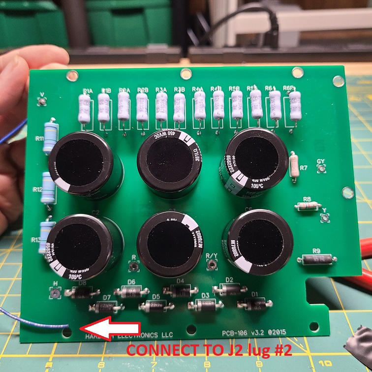
Reconnect the BLUE wire from solder pad “V” on the PCB to the insulated lug of the terminal strip. The insulated lug is the one on the right as per the picture above. Do NOT solder this wire yet. Picture below indicates the wire to connect the terminal strip lug.
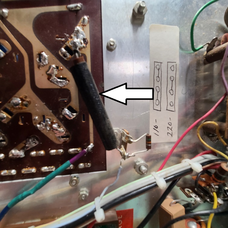
Connect the orphan 15K resistor from Part 1 of this series between lug #1 and lug #2 of terminal strip J and apply solder to both pads.
Reconnect HV Wire
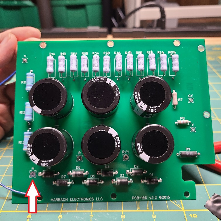
Solder the heavy BLUE HV wire to the solder pad marked “H”. Insert the wire from the bottom of the board and solder at the top.
Final Inspection
Installation of the board is complete. Double check all work and sure up any solder connections that may need it.
Reassemble
Its now time to reassemble the amp and prepare for the first power on test.
Front Faceplate
- Reconnect Front Faceplate
- Add control knob retention nuts
Control Knobs
Reinstall all control knobs, if knobs have position indicators remember to align them back the original position.
If a position is out of place during panel removal, realign by moving the control fully counterclockwise and re-install the knob.
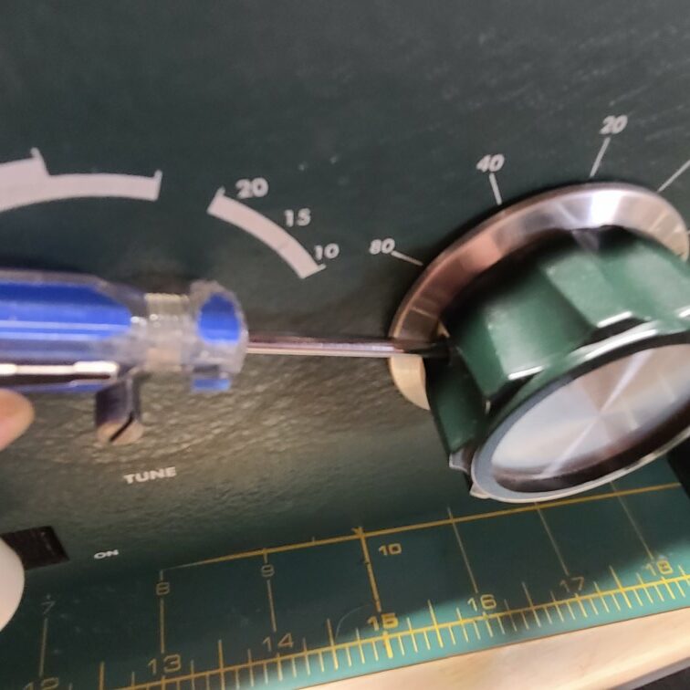
For the Tune control, which has 360 degrees of rotation, turn the shaft and watch until the moving plates of the variable capacitor are completely meshed. Reinstall the knob and align the position marker to the lower edge of the 80M visual indicator..
Tube Replacement
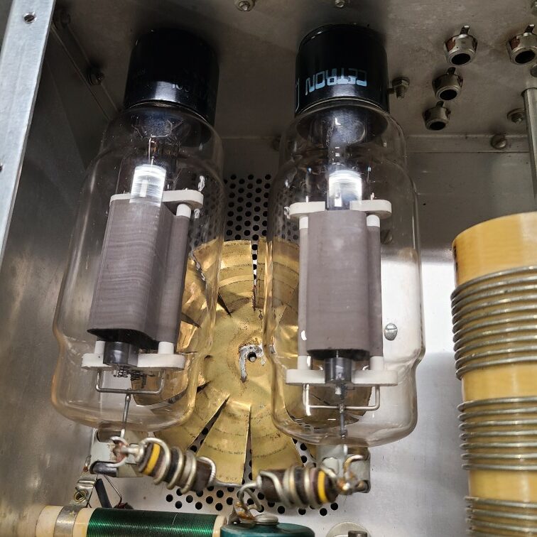
Replace the tubes and reinstall the plate caps. Take this opportunity to inspect the parasitic resistors and touch up any solder joints.
Final Button Up
- Replace RF Plate
- Reinsert Chassis into outer case
- Replace Rubber feet
- Close top lid
Powering on the amp
Safety
Significant care must be taken upon the first power up in case of mistakes. Use a variac to slowly ramp the input voltage up is recommended. Additionally, you may use an isolation transformer to the input of the variac for even greater protection. A variac is not required, but highly recommended.
At minimum, use an external power switch or outlet strip located away from the amplifier. This will provide a way to quickly turn things off without touching the amp.
Power on procedure
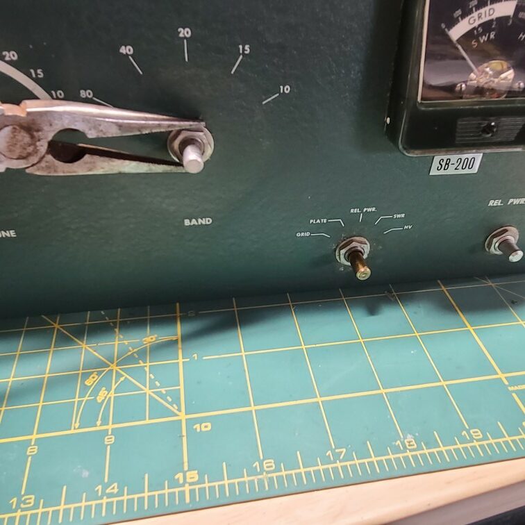
Making sure the amp power switch is off, place the meter selection knob to HV. Verify your outlet strip (or variac) is off and then plug the amp into it and turn the amp on.
Apply power
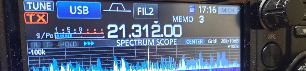
If using a outlet strip, turn it on and verify the amp’s power meter indicates 2000 – 2200 volts.
If using a variac, turn it on and slowly ramp up the power, you will see the amp’s voltage meter increase as you increase increase the voltage.
Testing
You may see the HV meter needle jump up and down a bit, this is usually caused by other loads in your house causing changes in the 120V line.
If you smell smoke, hear arcing, cracking, popping, or the HV meter is not registering any voltage, then shut off the power to the outlet strip or variac IMMEDIATELY. Do not use the amp’s power switch to turn off in the event that the problem has energized the outer case.
Troubleshooting
In the event of a problem, wait for all high voltages in the amp to dissipate before troubleshooting. Use the following checklist when troubleshooting.
- Verify all wires are soldered properly, in the correct location, and have all insulation intact.
- Look for component leads or wires in the chassis that may have gotten shorted during the installation process.
- Verify PCB components are inserted in their proper location and oriented correctly per their polarity.
- Look for any unsoldered leads on the PCB, also check for any cold solder joints.
- Verify the tubes are inserted correctly, seated firmly in their socket, and plate caps are attached.
- If all else fails, ask for help on heathkit.groups.io.
Load test
If everything checks out at this point, you can disconnect the amp from the external outlet strip / variac and plug it into your wall outlet and reconnect your rig.
Before placing the amp back into service, I recommend running a few tune up tests, on different bands, up to power and duty cycle rate your load bank can handle. Monitor SWR, HV, Plate and Grid Current for anomalies.
If everything checks out, your good to go!
73
AE8Q
good job, I’m a newbe to Heathkit amps.
Greetings:
I want to know if with 2,000 Volt. in the HV they are enough for the Heathkit SB-200 to work correctly. I have seen on “You Tube” videos where they appear up to 2,400 Volt. for exceptional performance. On the other hand, ask yourself if the programmable keys circuit is necessary to use the kenwood TS-590sg with this Amplify and if you have to connect it with the ALC cable.