If you are new to Winlink Express, performing the initial setup can be a daunting experience. Here is a quick start guide to get you on the HF bands using Ardop Winlink.
What is Winlink?
Simply, Winlink is a global radio e-mail system run by a network of Amateur Radio and authorized government stations to provide email services worldwide where internet is not present. It supports e-mail and plays a significant part in providing communications during times of disaster or emergency relief.
This tutorial assumes you have installed Winlink Express on a capable Windows computer and have a registered account setup. For more information and getting setup, visit http://winlink.org
To get started, you will need:
- Winlink Express
- A radio with built in Soundcard Interface -OR- a digital interface to your existing radio such as Tigertronics SignaLink or a Masters Communication DRA-45.
- You must have a registered e-mail account with Winlink.org
Initial setup of Winlink Express is beyond the scope of this post, buy hey, I may cover setup in a future tutorial.
Start a WinLink Ardop Session
Step 1 – Launch Winklink Express and select “Ardop Winlink” from the Open Session Menu and then click the “Open Session” button next to the selection.
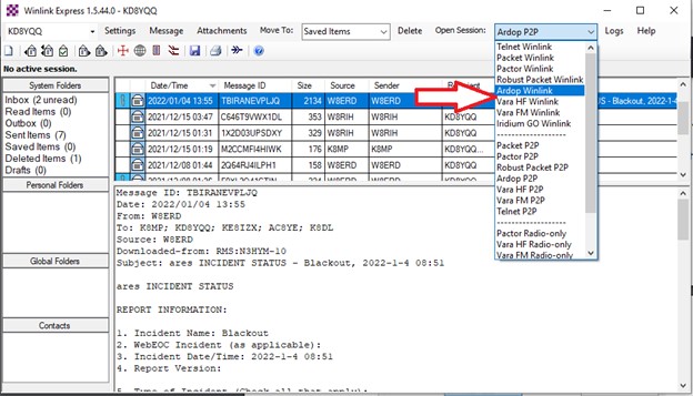
Step 2 – After a short delay of a few seconds, the Ardop Winlink Session window appear, along with a second program called ARDOP_WIN Virtual TNC. The TNC app will usually launch minimized, but you should see the icon at the bottom of the screen as indicated by the arrow in Figure 2.
Setup Ardop TNC Virtual Modem
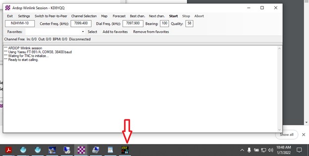
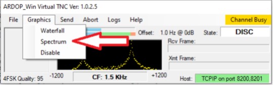
Step 3 – Click on the icon to maximize the Ardop_Win TNC modem. (NOTE: On older versions of Winlink Express, this may be something else, best to upgrade if you are running an old version). Below is a picture of the Virtual TNC as it appears on my setup. By default, the signal window will show a waterfall but I like to show the Spectrum view as it is more informative per Figure 3.
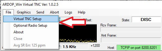
Step 4 – Configure the Virtual TNC to work with your Rig…. Select Virtual TNC Setup from the File Menu as per Figure 4
Step 5 – Setup your Radio’s Soundcard settings where noted by the arrow. In my case I am setting the FT-991a soundcard. Your soundcard names will look different as I have configured custom names for mine in Windows 10. Most likely, the Soundcard Names on your system will contain the words “USB Audio Codec” if you are a rig with built in soundcard, Signalink or DRA-45 adapter. They may contain other names depending upon your particular setup.
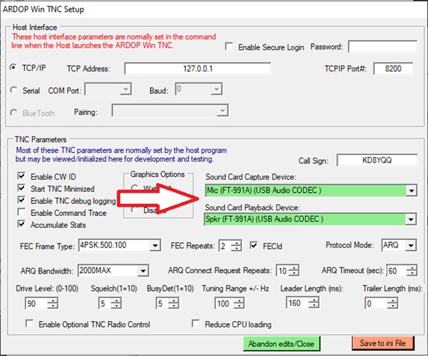
Step 6 – The rest of the settings in Figure 5 work well for me. I usually turn off “Start TNC Minimized” as I like to look at it during a connection exchange. Don’t forget to set your Callsign for CW identification to work properly, otherwise the application will generate a fault anytime you go to connect.
Step 7 – Select Save to ini File once complete. NOTE: After doing this, there may be a delay were the menus on the ARDOP Winlink Session window grey out and can’t be used. They will return to normal after the ARDOP TNC program re-initializes, this can take up to 30 seconds.
Optional Radio Setup
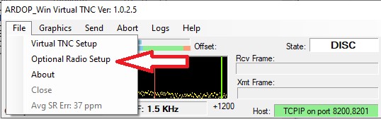
Step 8 – There is another menu option, Optional Radio Setup as shown in Figure 6. These parameters are set automatically by Winlink Express when a new session is started, you can just ignore it for now… If you do make any changes here, they will be erased and reset the next time you open a new Winlink Session.
More WinLink Session Settings
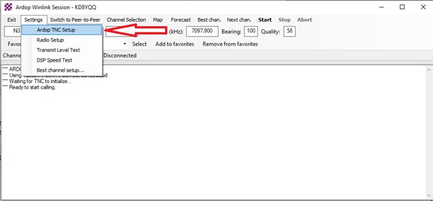
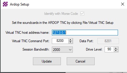
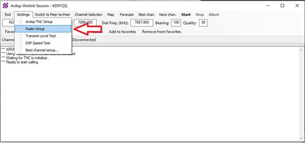
Step 9 – Next, navigate back to your ARDOP Winlink Session window and select ARDOP TNC Setup as per Figure 7
Step 10 – Verify your settings match those in Figure 8
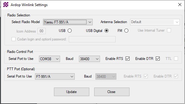
Step 11 – Press the Update button to return to the “Ardop Winlink Session” window and then select Radio Setup as per Figure 9.
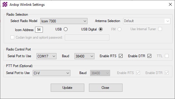
Step 12 – In the Ardop Winlink Radio Settings window, set your radio options. I have included my settings for the FT-991a, ICOM-7300 and Flex Radio, all of which I either own or have access to. Your COM port numbers will be different then mine.
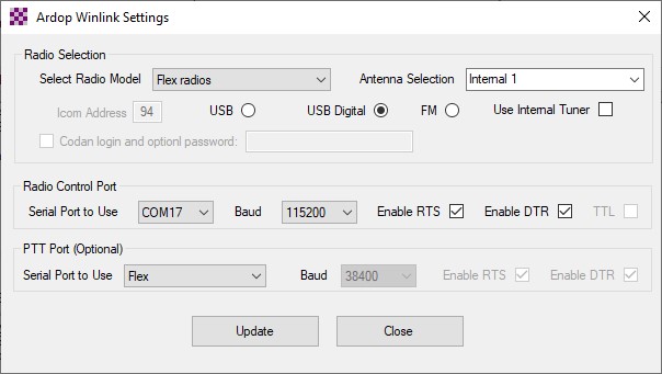
Step 13 – Once you have your rig configured, press the Update to return to the session Window.
HF Channel Update
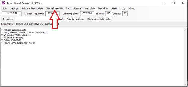
Step 14 – Next, find a usable HF channel by selecting Channel Selection
Step 15 – WinLink may ask if you want to update the list based upon recent Solar Flux Index / Propagation reports, allow it to do so if it asks.
Step 16 – Next you will see a list of stations in close range… Select any station on the list, but the first few will usually give you the best chance of success.
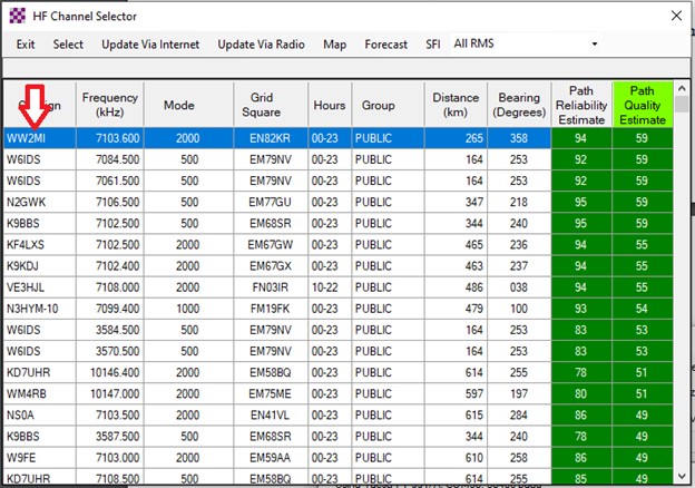
Step 17 – Next, check your rig, the frequency on it should match the frequency you selected in the list. If it does not, then there is a setup issue, most likely from step 12 above. If the radio does change frequency, then you are almost ready to begin transmitting.
Pre Flight Checks
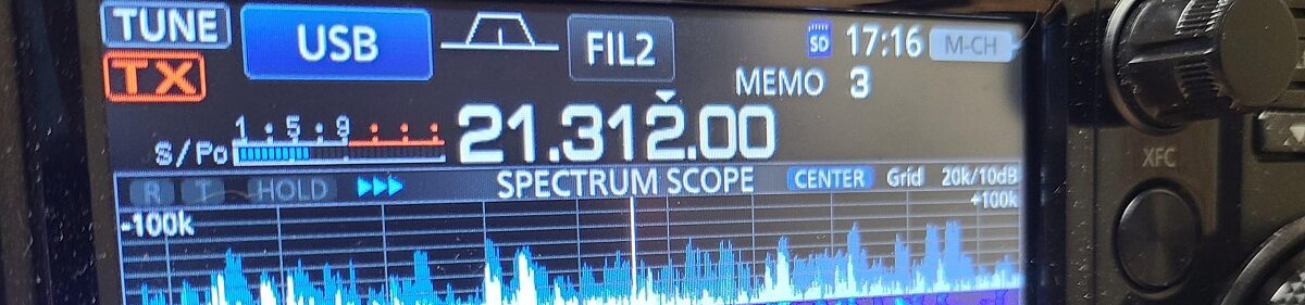
Step 18 – Even though you have connectivity, WinLink does not always setup your rig correctly so you will want to manually verify the settings on your rig. Here are the ones to look for..
- Rig Frequency: Should match the dial frequency specified in the Ardop Winlink Session window.
- Rig Mode: Upper Sideband – Data
- Width: 2000, 1000, 500 To Start with, I like to set my Width to 3000 Hz for testing, however I usually change it to match the “MODE” setting in the channel selection table above for whatever channel is used as it improves decoding of the ARDOP signal. However, that is optional.
Step 19 – Go back to the ARDOP Winlink Session window and perform a Transmit Level Test
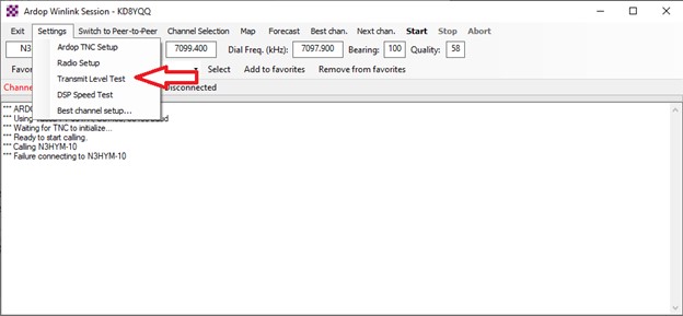
Step 20 – If everything is working, you should see the radio keyup and the rig will transmit a series of tones for a few seconds. (You may want to reduce TX power before performing this test). You will also see the power output of your radio oscillating up and down as the tones are being sent.
Time to Transmit!
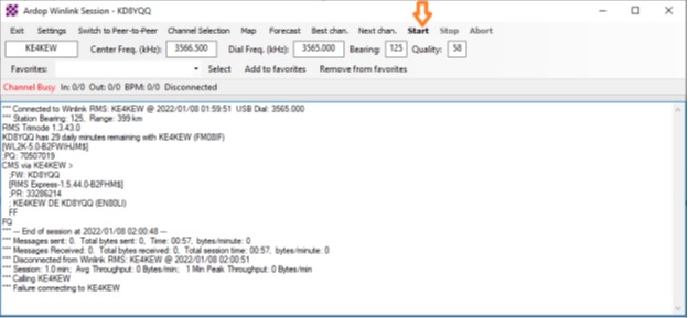
Step 21 – If your setup is good at this point, you should be able to select Start on the Session menu and hopefully make a connection. If no connection is made, select a new channel from the Channel Selection menu or click Best chan. or Next chan. to have WinLink search for one for you.
Additional Notes
It is a matter of preference, but I think the waterfall display on the ARDOP_Win Virtual TNC program is useless and find that showing the Spectrum proves to be more informative. It is a matter of personal taste, but you can change it if you wish by selecting Spectrum from the graphics menu.
Also, I like to keep the application maximized and watch it during and exchange with an HF server I find it to be very informative in showing what is going on with the Exchange.
Good luck and happy e-mailing!
Ed – AE8Q
Interesting and helpful. Any idea on how to add the CAT commands for the Icom IC-718 transceiver would be appreciated. I’ve tried asking on the ICOM forum but no responses after several days of waiting. I suspect few want to admit owning an using a “cheap” Icom.
73
de Dave Mann N4CVX
I think the address may be incorrect… Go back to Step #12, and put 5E in for the CI-V address and see if that works for you. 5E is the default CI-V address for the ICOM 718
Ed
Also, I forgot to mention, if changing to 5E alone does not work. Try some of the other ICOM Radio Models from the dropdown list. After selecting one, verify the Address is still set at 5E
73
Ed AE8Q
I am quite new to Winlink, and so this may have an obvious answer. I will be setting up Winlink and ARDOP for Winter Field Day, away from the Internet.
Obviously, the registration for Winlink has to be done beforehand, using the Internet, but do your steps 15 and 16 require Internet connectivity to get the frequency list? What if I don’t have that connectivity?
Thanks, by the way, for this very clear tutorial.
Sorry for the really late on the reply on this I have had other things to work on and somehow missed it on my notification.
Internet capability is not required, it is possible to get a frequency list Update via Radio, which is listed as an option. It takes a bit, but should get you, I am not clear of the “magic” it uses to find the list, but will research once I have time.
I cannot get Ardop to work, I have an exe file and ini file. Havent tried in a while. Which version should work, and what subdirectory should it be in. I have it in the RMS express subdirectory any help would be appreciated.
Steve Rossi KS4YP
Sir – There are steps that use a dropdown list to pick your radio. My radio is an XIEGU model X6200. It is not in the dropdown list. Any suggestions on what to select for my ARDOP setup?
Thanks,
Mike AI5LL